

Falcon Anchors
Percussion Driven Anchors
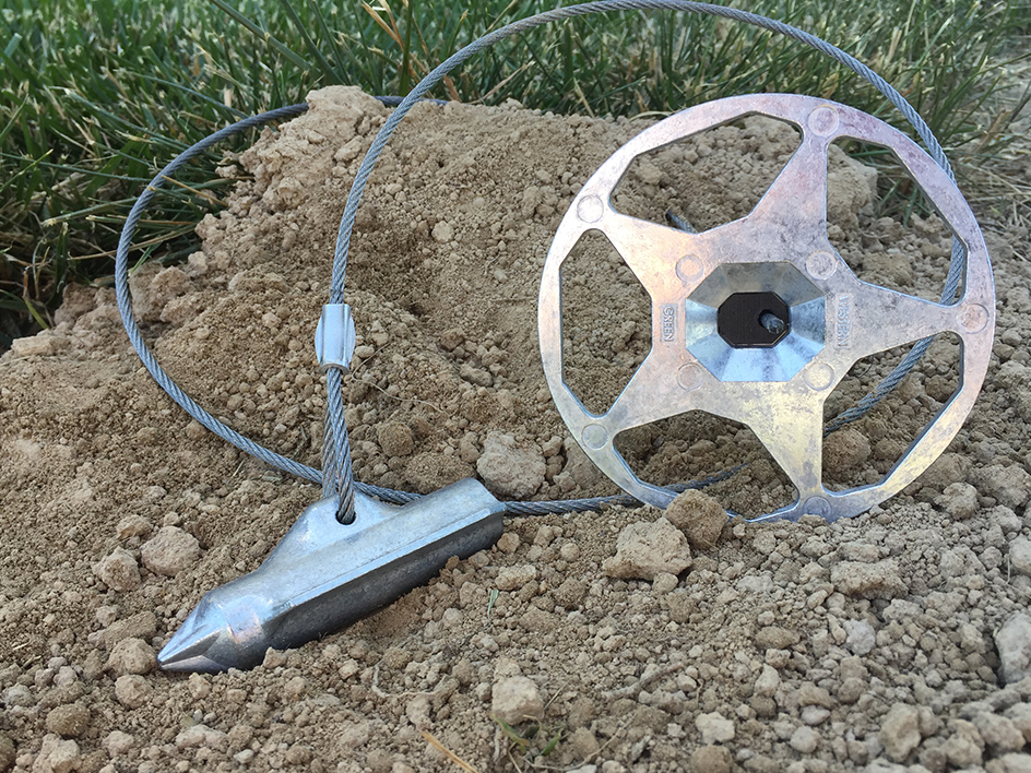
Western Green is proud to offer the Falcon Anchor line, providing securing hardware for Turf Reinforcement Mats (TRMs), High Performance TRMS (HPTRMs) and more. Falcon Anchors provide innovative, cost-effective solutions for erosion control and soil stabilization applications. Falcon Anchors are designed to provide immediate stabilization, requires no crimping and have improved load-locking capabilities and drivability, for easy installation. The Falcon Anchors are pre-assembled and are available in different configurations to best meet the specified project requirements and geotechnical conditions. Installing Falcon Anchors offers the performance needed while ensuring considerable time and labor savings.
Assembly Components
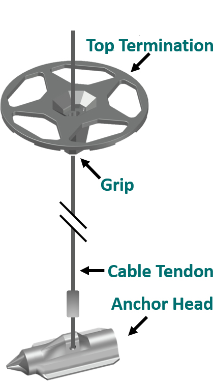
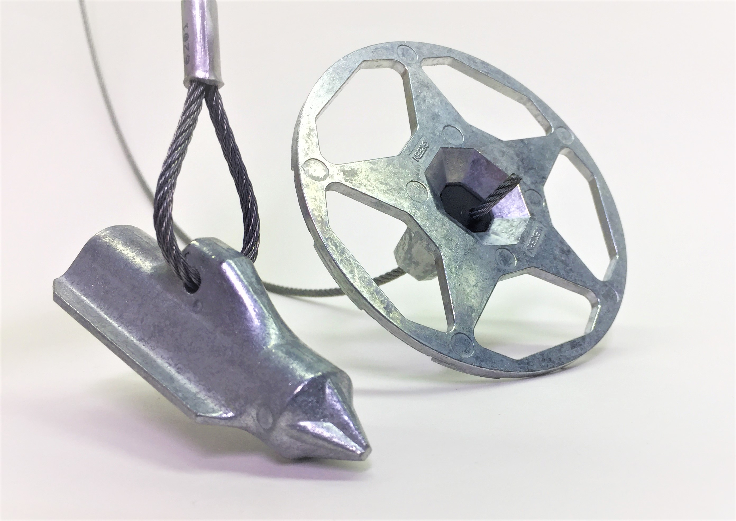
Anchor assemblies consist of four primary components:
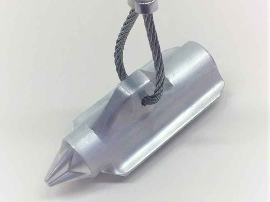
ANCHOR
The anchor is the component driven into the soil that develops resistance to pullout. The size, shape, soil type, soil conditions, and drive depth affect the pullout resistance of the anchor.
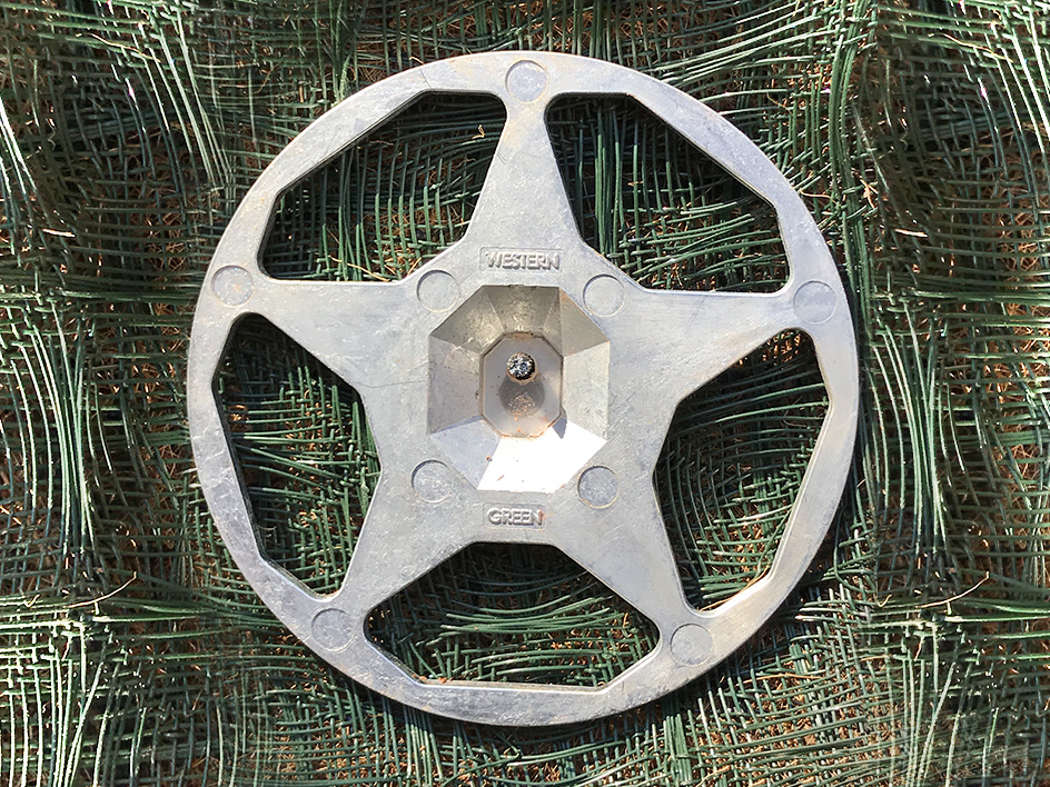
TOP TERMINATION
The top termination grips the ground surface and fabric to secure in place. The size of the load bearing cap effects the ability to hold the soil matrix. Openings in the termination aid in the establishment of vegetation, obscuring and protecting the hardware.
TENDON
The tendon connects the anchor and the top termination. Constructed of high-strength, corrosion resistant galvanized (zinc-aluminum coated) steel or stainless steel, the tendon is a critical piece for long-term performance. The tendon is typically fixed at the anchor side by crimping.
GRIP
The grip is housed in the top termination and secures the tendon in the top termination. A release mechanism can allow for re-setting the assembly, as required.
Each of these components can be varied to provide performance and economy options.
Variants, Applications and Performance
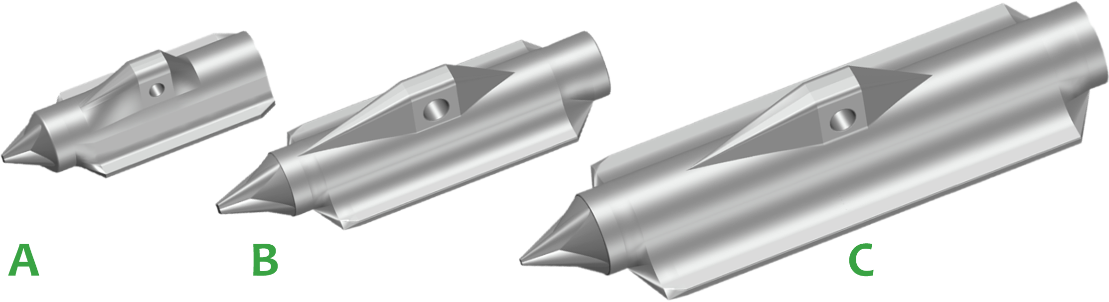
Anchors are available in three sizes. As the size of the anchor increases, working load and ultimate resistance increase:
F80 , Zinc Die Cast, Bearing Area: 3.4 in2 (image A)
F120, Zinc Die Cast, Bearing Area: 6.0 in2 (image B)
F170, Zinc Die Cast Bearing Area: 12.2 in2 (image C)
Top Terminations are available in 2 sizes. Durability and working load increase with size.
The top termination uses a unique design to allow for optimized working load, while still allowing vegetation establishment. The termination plate is selected based on the anchor size and cabling configuration. The small termination is 4” diameter, while the large termination is 6” diameter.
Table of Configurations
Assembly/Part | F80-X-Z Series | F120-X-Z Series | F120-SW-Z Series | F170-SW-Z Series |
Cap | 4” Dia. Zinc Alloy | 4” Dia. Zinc Alloy | 6” Dia. Zinc Alloy | 6” Dia. Zinc Alloy |
Grip | Spring-Loaded Ceramic Crush Roller | Spring-Loaded Ceramic Crush Roller | Spring-Loaded Ceramic Crush Roller | Spring-Loaded Ceramic Crush Roller |
Cable | 1/8” Dia. ZA Coated Extra Strong Steel, 3 ft Typ. | 1/8” Dia. ZA Coated Steel, 6 ft Typ | ¼” Dia. ZA Coated Steel, 6 ft Typ. | ¼” Dia. ZA Coated Steel, 6 ft Typ. |
Anchor | 3.4” (80mm) Zinc Alloy | 4.7” (120mm) Zinc Alloy | 4.7” (120mm) Zinc Alloy | 6.7” (170 mm) Zinc Alloy |
Typ. Working Load | 750 lbs | 750 lbs | 2,500 lbs | 3,000 lbs |
Max. Working Load | 1,300 lbs | 1,300 lbs | 2,700 lbs | 3,500 lbs |
Ultimate Assembly Strength | 1,500 lbs | 1,500 lbs | 3,000 lbs | 3,800 lbs |
Ultimate Cable Strength | 2,000 lbs | 2,000 lbs | 7,000 lbs | 7,000 lbs |
Typical Use | Workhorse Light Assembly | Soft Soil Workhorse Light Assembly | Hard Soil Heavy-Duty Assembly | Heavy-Duty Assembly for Soft Soils |
Installation
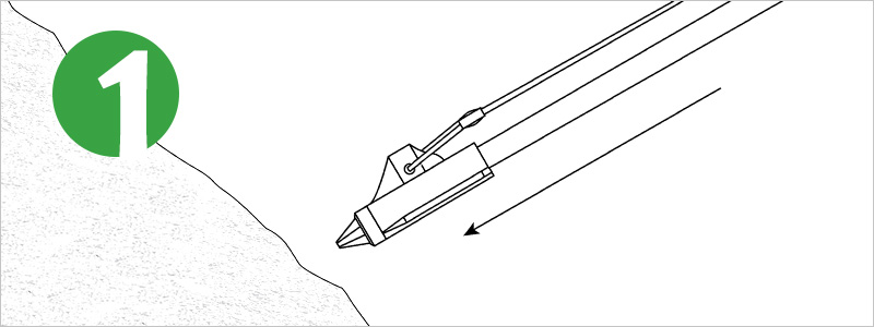
Step 1
Insert the drive rod into the Falcon anchor head and place perpendicular to the slope. Insert drive rod with anchor head swiftly through the mat in the desired location.
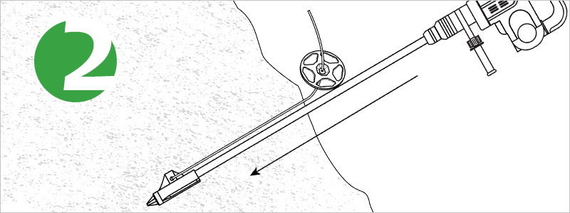
Step 2
Drive the Falcon Anchor to the desired depth. Anchors can be driven using sledge hammers, gas powered drivers, or hammer drills.
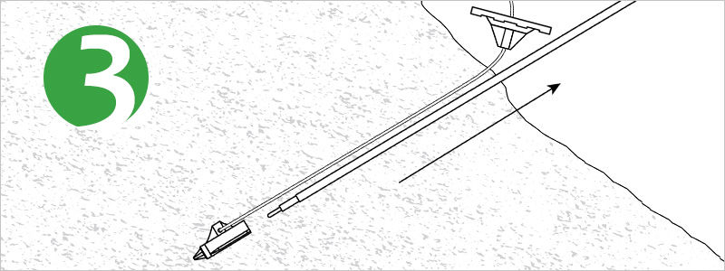
Step 3
Remove Drive rod. In soft soils, the drive rod can be removed hand, in tougher soils the use of a jackjaw may be required.
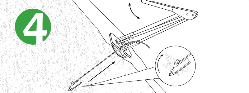
Step 4
Load lock the anchor once the rod is removed. Slide the top termination flush to the ground. Place Jackjaw baseplate directly over the top termination cap. Ensure the cable is in live with the JackJaw jaws. Handle must be in the up position to open jaws. Move the lever handle in a full down/up motion. Pump until resistance is felt. The top termination cap will appear slightly recessed in the mat once the anchor is appropriately load-locked.
Resources
Falcon Pins
The Falcon Hex Pins are an innovative fastener providing significantly greater pullout resistance than typical straight pins or staples. Available in configurations specialized for different soil types, the Falcon Hex Pins improve pullout performance in soft or sandy soils, as well as compact, cohesive soils.
Click to Learn More

